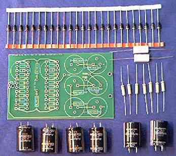
Uh, seven bleeder resistors? The board only has holes for six resistors. The seventh one is to drop onto the shag carpet, never to be seen again. Likewise, there is room only for 24 rectifiers. We include 26 of that part because the leads are pretty stiff. If you break two of them while bending the leads, there will still be enough of them to complete the job. The rest of the parts are big enough and stout enough that you probably won't break or lose them.
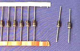
Next you need to clip the rectifiers loose from the tape. Leave the leads long enough that they won't be tricky to bend. I should consider bending them before we pack the kit. That way you wouldn't need to. It's a pain in the neck. Or in the fingers.
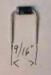
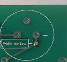
Next, bend the leads parallel on six of the 240k 2-Watt bleeder resistors.
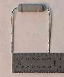
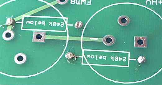
Insert them into the UNDERSIDE of the board, BENEATH the spot printed on the top side of the board. .
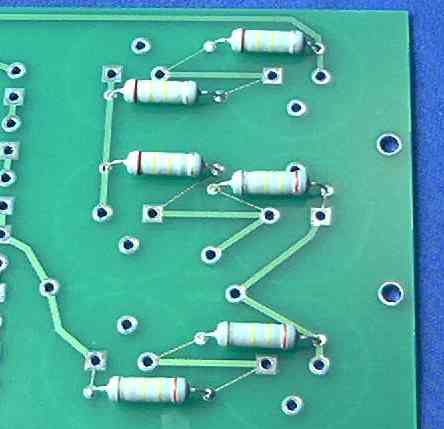
Solder the resistor leads to the board, then clip all twelve bleeder-resistor leads as flush to the board's surface as you can.
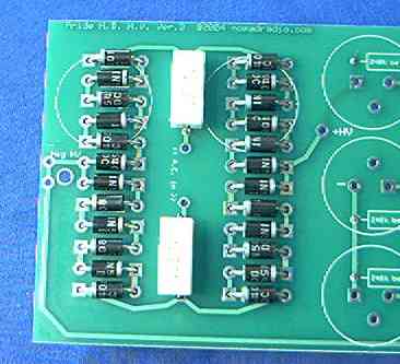
Next come the rectifier diodes. If you are qualified to install this thing, then I don't have to explain that the white band at one end of each rectifier is the cathode. That end of each rectifier goes to the SQUARE hole, the other (no band) end goes to the round hole for each diode outlined on the top side of the board.
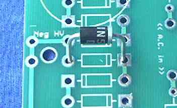
You are welcome to do this in any sequence you like, but I have a suggestion for keeping the rectifiers all pointed in the right direction. IF YOU GET ONLY ONE OF THEM BACKWARDS, IT WON'T WORK RIGHT. Guaranteed..
First, insert only the twelve rectifiers that point to the right. That is, the ones with the banded end (and the square hole) on the right-hand side.
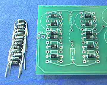
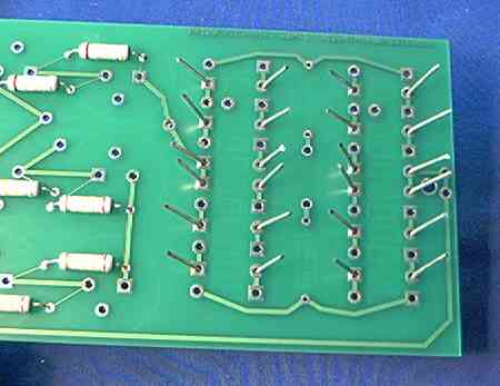
As you insert each one, bend the leads sticking out the bottom apart at about a thirty-degree angle so they won't fall out when you turn the board over later to solder them.
Now insert the other twelve rectifiers, the ones that point to the left. This is a good time to insert the two 5-ohm 5-Watt resistors, also.
Make sure that you bent all 52 lead wires outwards so they won't fall out of the board, and turn it over to solder them.
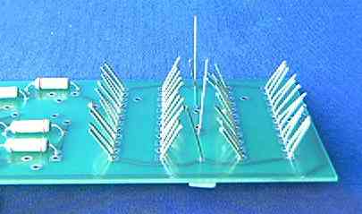
Once you have soldered all 52 leads and clipped off the excess, it's time to insert the six electrolytic filter capacitors.
Each one has a white stripe along one side, and a minus sign (-) printed on that side.
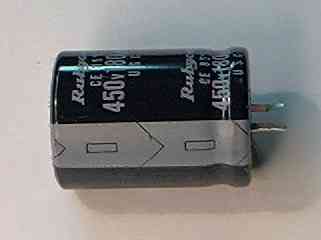
This pin on the capacitor goes to the ROUND hole at each position. Just for good measure, there is a white "-" printed alongside the round hole for each filter cap.
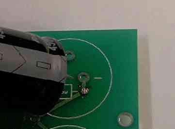
The pins on these capacitors are bent so that they will "snap" into place, and prevent them from falling out when you turn the board over to solder them in. Here's how they look, all six turned around the right way. Take a moment to compare here, before you solder them in. IF YOU ONLY GET ONE OF THEM BACKWARDS, IT WON'T WORK RIGHT. Guaranteed.
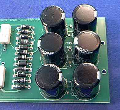
Now solder all twelve filter-capacitor pins. The board is now ready to install.
You'll need to use the "Back" button on your browser to return to the installation procedure, because I can't figure out how to simulate it with an html tag.