|
Installing the Nomad Radio KeyBoard v.2 in the RCI 2990 DX
Copyright 2003 nomadradio.com
Preliminary version 0.2 07/01/2003
|
--> Introduction: What's it good for? Why bother?
Traditional multiband amateur HF transceivers come with a built-in
facility to enable or "key" an external amplifier using just an
appropriate patch cable. Current 10-Meter Amateur transceivers
are sold universally WITHOUT this feature.
The Nomad Radio KeyBoard installs inside these radios. It contains a 5
Amp-rated relay that is connected to TWO spare sockets on the rear
panel. These sockets are labeled "Counter" and "Rec". Just who needs an
external frequency counter on a radio with built-in digital frequency
display ???. Sounds like a spare jack to me. Likewise the Tape Recorder
output. A patch cable from either the "Counter" OR the "Rec"
socket to the amplifier's relay or VOX input will place
the amplifier in line WHEN THE MIKE BUTTON IS PRESSED, and return it to
standby when the mike switch is released.
Kiss that foot switch goodbye. The relay in an amplifier will last
longer if it is engaged only BEFORE the radio produces drive power. If
the amplifier is keyed AFTER the drive is feeding to it, an arc will
form across the gaps in the relay. This accelerates wear and tear. If
you are repeatedly "late" with a foot switch, the amplifier's relay
contacts will
burn and wear out prematurely.
Can't tell how many folks will need the second jack. It's there for
folks who use a "driver" amplifier with a QRP radio.
|
 |
Step Zero (The one I remembered last). -- Unplug EVERYTHING
-- Press the "Power" switch. The lights will flash, then fade. This
bleeds the stored energy in the power supply. Much safer that way.
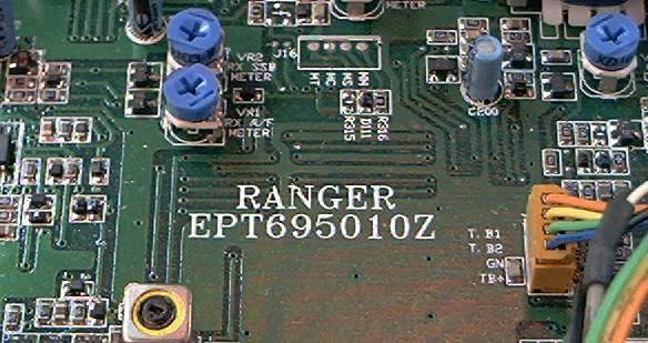
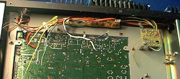
Remove the covers, top and bottom both. Check the top side of the main
circuit board for a type number printed in white, just to the right of
the board's center. This instruction page is for a radio with the
number "EPT 695010Z". If yours is different, the pictures of circuit
board foil patterns on this page probably will not match your radio.
The very last letter of this "circuit-board number" is called the
"suffix" and may be different from the one in this picture. If
the layout of your unit looks the same as in the pictures below, you
can ingore that last letter, if it's different.
|
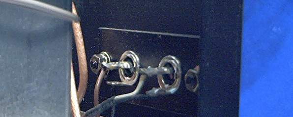 |
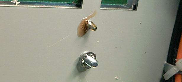
| Step 1: Unsolder both center wire and shield from the
"Counter" jack. |
 |
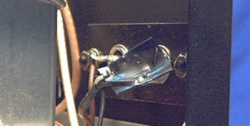
| Step 2: Tape the bare ends of the cable so they are
separated from each other. |
 |
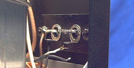
| Step 3: Remove the brown and black wire pair from the
"REC" jack. |
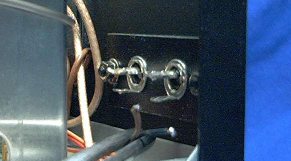 |
| Step 4: Clean the tip of the soldering iron with a
paper towel folded four or five times. Moistening it helps... a little.
Now "dab" as much solder as will transfer to the iron tip, from one of
the four socket pins. The iron tip will "soak up" a little of the
solder that is blocking the holes in the lugs. Remove the 'dabbed'
solder with the towel, and repeat until BOTH lugs on EACH socket have
the hole reopened. This is so you can stick more wires back into them
in a little while. |
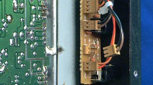
| Step 5: Now turn the radio up onto its left side. At
the other end of the brown/black wire pair is a tan 2-pin socket
underneath, plugged into the circuit board behind the external speaker
jacks. This small 2-pin socket will have "J 181" printed in white next
to it. Pull the socket. The brown and black wires will now pull loose
from the bundle. |
 |
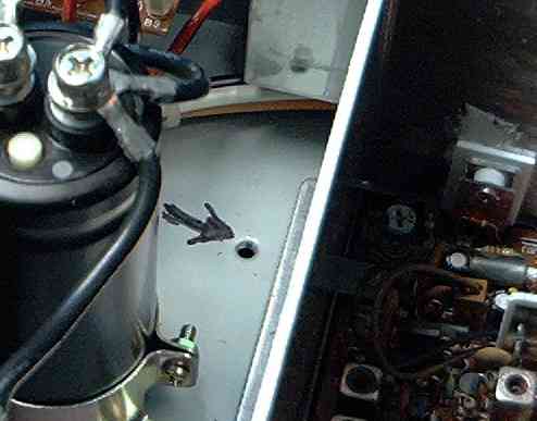
| Step 6: Find the spare chassis hole to the left of the
main circuit board. |
 |
| Step 7: Take the 6-32 screw with the captive
lockwasher, and thread it into the topside chassis hole as shown. |
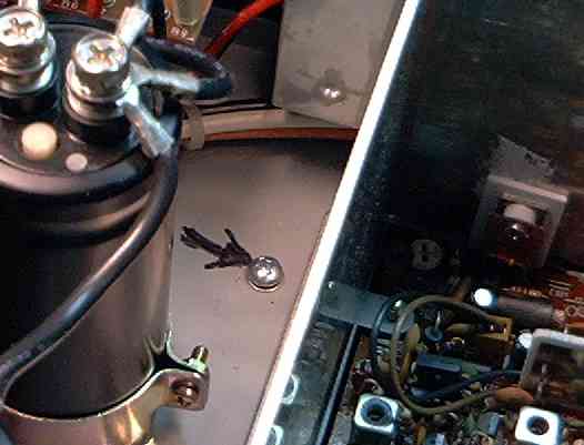 |
| Step 8: Slide the loose lockwasher over the screw
where it protrudes under the chassis. |
 |
| Step 9: Now screw the threaded standoff down. Tighten
both of the screws on both ends of the standoff. |
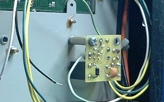 |
| Step 10: Route the five long wires along the back
panel, alongside the fat black and orange DC power leads. |
 |
| Step 11: Feed the two yellow wires and the dark green
wire through the hole at the rear corner, under the "Counter" and "Rec"
jacks. Twisting the ends of these 3 into a bundle may make this easier. |
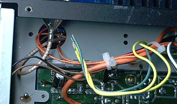 |
| Step 12: Lap-solder the black wire to the ground trace
just to the front from where the fat black wire attaches to the main
circuit board. |
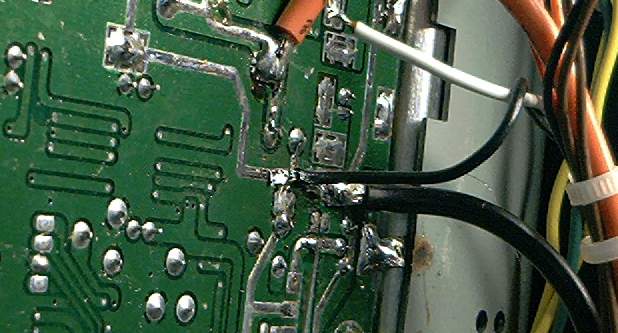 |
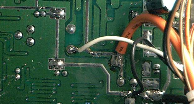
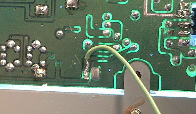
| Step 13: Lap-solder the white wire to the round foil
pad shown in the picture. This is a lot easier than trying to melt the
solder on that fat orange wire. |
 |
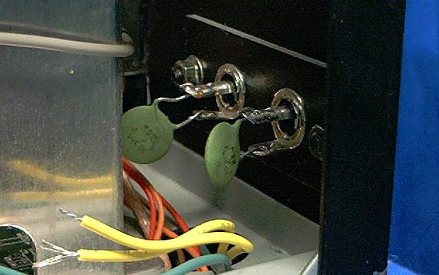
| Step 14: Turn the radio back right-side up, and insert
each of the .01uf 1KV disc capacitors in each of the sockets. Don't
solder them yet. |
 |
| Step 15: Insert the long, stripped end of the dark
green wire into the LOWER lug of the "CTR" jack. |
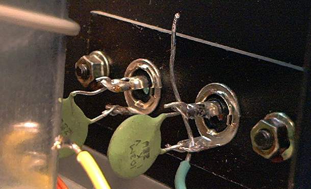 |
| Step 16: Thread the end of the wire into the lower lug
of the "Rec" jack. Now solder the lower lug of each jack. |
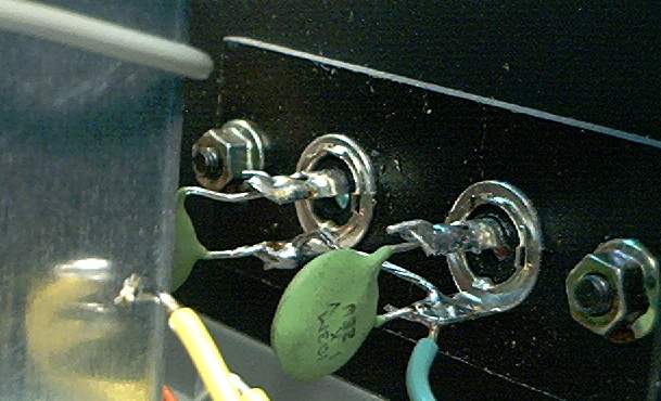 |
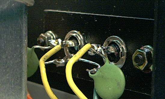
| Step 17: Insert the stripped ends of the yellow wires,
one into each UPPER pin of the two sockets. Doesn't matter which yellow
wire goes into which socket. Solder them both. |
 |
| Step 18: The short light-green wire goes to the
switched 8 Volts on Transmit ONLY. The easiest place to attach it is
shown in the picture. |
 |
Step 19: Double-check for accidental splashes of
solder near all three wires that you have just attached to the main
circuit board. You may want to plug in the antenna, mike and power cord
before installing the top and bottom covers. Try the radio and see that
it still works, THEN re-install the covers and handles.
Now, put that old foot switch on E-bay before I put this kit on the
market. |