Now
that you have agreed NOT to reach inside your amplifier and damage
yourself, we can discuss one of the most aggravating 'weak spots' in
the design of this very-popular base-station amplifier.
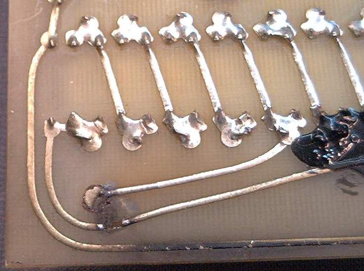
The 2400-Volt DC power needed for the plate circuit in the DX300 is
rectified and filtered on two printed-circuit boards that slide into
plastic guides, directly beneath the large High-Voltage transformer.
Each of these two boards has half of the rectifiers, and half of the
filter capacitors/bleeder resistors. A rat's nest of jumper wires joins
the two boards to provide a full-wave bridge rectifier circuit, and a
series string of six 450-Volt rated electrolytic filter capacitors.
Together, they add up to a breakdown-voltage rating of 2700 Volts (450
times six). Trouble is, they placed many of the foil traces on these
two boards close enough to arc and break down, like the one in the
picture above. The black paint at the right of the picture was applied
at the factory, to prevent this problem. Too bad they didn't use more
of the stuff. If you have a new unit that has NEVER been used, this
trick will probably work, if you apply the stuff at all the other spots
where the foil traces are too close.
More likely, your DX-300 has had some amount of wear and tear occur
since it was built in 1977 or 1978. If it looks more like the one
below, you might be looking for a better solution.
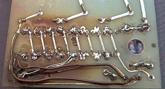
You could always strip the foil from that whole end of the board, and
do it this way.

Our approach is to completely remove the original two H.V. circuit
boards and install the single-piece replacement you see
below.
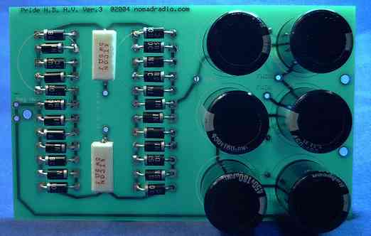
For now, we are selling this solution only as a kit; circuit board and
parts. When it's assembled it looks like the picture above.
The tentative sale price for this first batch is US$90.00, prepaid and
includes USPS Priority Mail shipping to USA destinations
ONLY.
*** UPDATE ***
8/22/2004 ***
We got
the boards, and shot the pictures. The instructions to build the board
from the parts kit we supply are here: Assembly
Instructions
To start, UNPLUG
EVERYTHING !!! Really ....
Remove
the top cover, and make certain that the high
voltages have bled off. Press the point of a long INSULATED screwdriver
to the
chassis deck, and touch the side of the blade to the large
hairpin-shaped copper or brass strap that's bolted to the tube clamp.
This is to bleed off any remaining charge that is stored in the old
filter caps. If you see EVEN A SMALL SPARK, hold the
screwdriver
blade there for several seconds. Move it away slightly, and try this
once more. Continue until you can see NO SPARK at all when the
screwdriver shorts the tube clamp to ground.
Next, you need to remove the bottom cover plate.
Once it's off, with the bottom of the amplifier face up, unplug ALL the
old wires from the two circuit boards that are directly beneath the big
high-voltage -transformer.
- Unplug
all the
wires from the two boards, and remove them. You should
have
- One
thick red
wire that leads to a rubber grommet that leads to the
topside of the amplifier.
- Two
not-so-thick red wires that lead to a rubber grommet up to the
large HV transformer above.
- One
short black
wire that is soldered to a ground lug against the front
of the lower compartment.
- A
long yellow
wire that leads all the way across the underside to the
"Metering" socket on the rear panel.
The long yellow wire really just needs
to go away.
Clip it at the rear of the "Metering" socket. The Version 1 HV board in
the pictures does not have a hookup for the yellow wire on it. The
"kit" version of the board, Version 3, will have a place for this wire
to connect. If you will be using the Pride for AM, the yellow wire is
pretty useless. The 'factory' procedure to set the bias control using
the "Metering" socket is pretty lame, anyway.
Remove the push-on socket contact on the
end of each
of the remaining four wires. Strip approximately 3/8 inch
from
the end of each. Tin the stripped ends with solder. This will
keep the loose strands together. Also makes it solder to the hole in
the new board with less heat.
Here is where they go on the new HV
board.
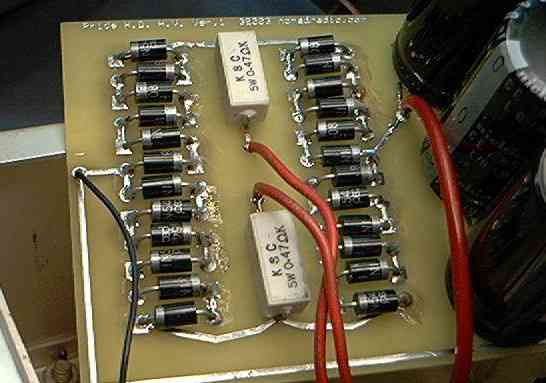
Each
of the two skinny red wires goes to one of the two holes marked "AC".
Doesn't matter which of the two wires goes to which hole. It's A.C. It
won't care.
The fat red wire goes to the hole marked "+HV".
The short black wire goes to the hole marked "-" (minus). Or to the
hole marked "Neg HV". It's the same hole either way. The way it's
marked depends on which version of the board you have.
Take
a good look at the other end of the short black wire. It is soldered to
a ground lug under a sheet-metal screw. Make sure the screw is tight.
If it strips the soft aluminum chassis metal, and spins without ever
getting tight, you have two choices.
1) First, get a ground lug with a large enough
hole for a
#8 screw. Now crank a #8 sheet-metal screw into the hole. It should
hold tight now, and not spin like the original screw did. Remove the
short black wire from the old ground lug and solder it to the new one.
OR
2)
Get a #6-32 by 1/2 inch long machine screw, and a #6-32 nut. A
Philips-head screw may be easier to turn at this angle than a screw
with a slotted head. Crank the screw into the old hole, with the ground
lug under the head. Thread the nut onto the end of the screw that now
sticks out into the front section, where the Tune, Load and Band switch
controls are. Tighten the screw until the nut is drawn down tight. Now
you have a ground connection on that black wire that you can trust.
When you have attached all four wires to the board, it will slide down
into the plastic rails nearest the outside.
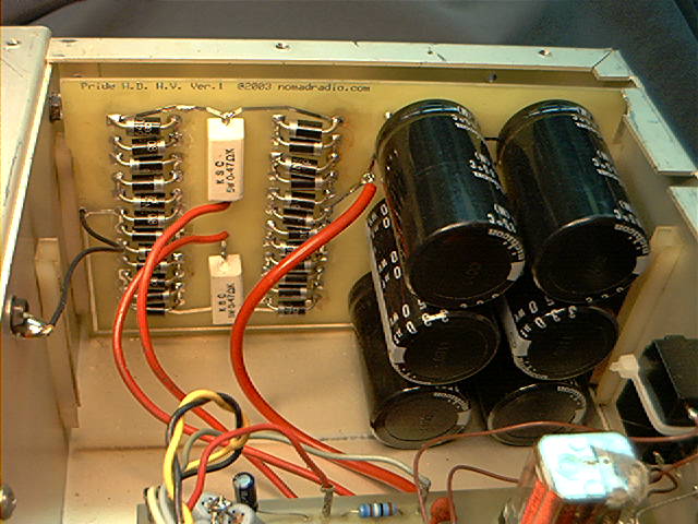
Before
you put the bottom cover
back and fire up the amplifier, be SURE that the tube is securely
pushed down into its socket. It will come loose while the chassis is
turned upside-down.
There is a lengthy list of "Anti-Suicide" measures that we recommend
for the Pride DX300.
- The other two circuit
boards
in the bottom conpartment have all the wires attached to them with
small spring-metal socket contacts. Pull each of the socket contacts on
all the wires, (one at a time, of course). Any of them that feels loose
when you pull on it should be GENTLY squeezed with a small pair of
pliers so that it has some friction when you push it back onto its
circuit-board pin. Yeah, I know. It sounds like a bore. Do it anyway.
It's important.
On
the small
circuit board bolted to the rear of the meter, the output coax should
be SOLDERED DIRECTLY TO THE BOARD. First unplug the two coax cables
from it. Loosen the nuts on the meter posts, and GENTLY pull the board
away from the meter body.
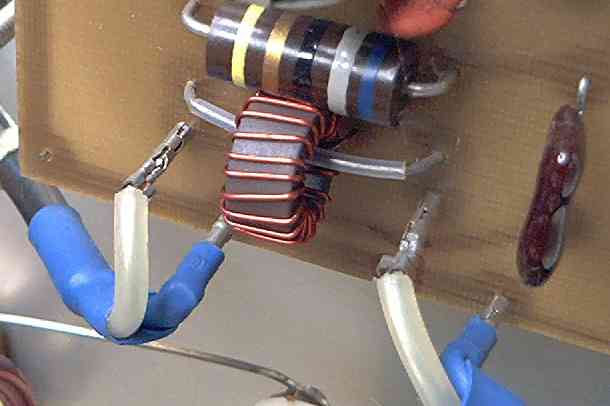
You will need to unsolder the bare ground wire from the
inboard-lower corner.
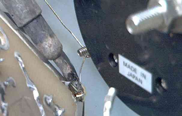
Heat the solder under the four pins where the two coaxes were plugged
in, and pull them completely out of their holes.
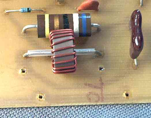
You
will need to ream the two ground holes (the ones on the outside edge)
out to a hole size of about 3/32 of an inch. You also need to clear any
leftover solder from the two holes where the coax center wires attach.
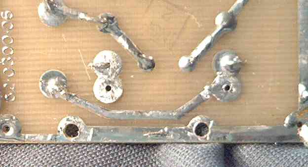
Remove
the spring contacts from
both the coax cables that you unplugged from the meter board. Strip
about 3/8 of an inch from the end of each. You should also pull off the
shrink tubing that covers the coax braid. Tin each of these wire ends
to hold all those loose strands together.
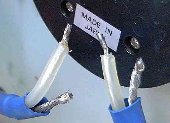
Now insert the tinned wire ends back into the four holes in the meter
board. Solder them in place, and that skinny bare ground wire on the
corner of the board.
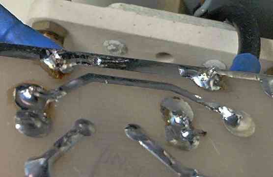
When the meter board is mounted back onto the meter posts, it should
look like this.
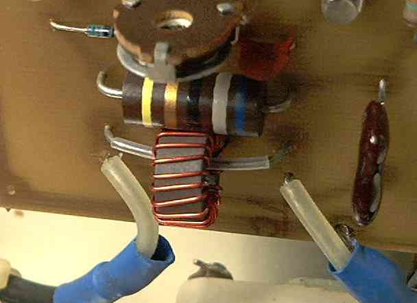
The coax on the outside-facing side of the meter board heads straight
down, and into a bundle of wires. Make SURE that this coax is not too
close to the brass nut on the end of the Plate Tune control's white
ceramic insulator . It should be at least a half inch away from it. If
not, an arc could jump from that brass nut through the outer plastic of
the coax, to the ground braid INSIDE the outer black jacket. Just don't
let the coax touch that nut. It has High-Voltage RF on it when the
amplifier is delivering power. The other end of this coax is
underheath, between the larger relay and the RF Output socket, That end
should also get the pins removed, and soldered directly. For now, you
are on your own getting that done.
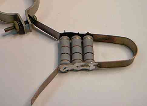
Now would be a good time to take a close look at that big copper
hair-pin that attaches to the tube clamp topside. If it looks like
this, new resistors should be installed before you try to run it.
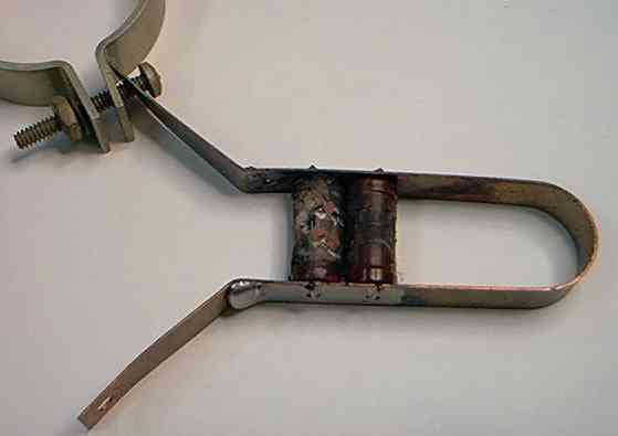
If the resistors look okay, and it has all 3 of them, leave it alone.
If you replace them, we recommend using a 5-Watt rated 100-ohm
carbon-film or metal-film resistor. They will withstand more
abuse than the original 2 Watt-rated parts. DO NOT use wirewound
resistors. Period. Both Mouser Electronics and Westgate Labs sell this
resistor.
Before you put the covers back on and plug anything in, you really
should remove the main fuse in the back, and check the rating printed
on it. The correct size is 10 Amp, 125 Volt or 250 Volt. A 32-Volt fuse
is NOT the right type for this amplifier.
Since you are supposed to know what you are doing, we'll skip the
step-by-step procedure to reassemble and safely test the amplifier.
Keying Circuit
"suicide-prevention" parts kit....
Revised additions 6-19-05
Below is a shot of the main pc board (relay board) with the
keying-circuit upgrade installed. The notes on the pic will be
sufficient for anyone with a schematic (and two eyes). Maybe
I
should give this procedure the step-by-step treatment, but not today.
Maybe I'll throw in the pic showing a hole burned completely through
the main circuit board (between the two relays), where R46 flamed out
and burned the epoxy. In a nutshell, the procedure below will fix the
"R46 burns up" problem, and make the keying circuit MUCH more
poof-resistant. Oh, and the larger new transistor will comfortably key
an additional relay coil, if you choose to add one.
THERE IS ONE DRAWBACK: The
sensitivity of the keying circuit will
be reduced on the 80 through 20-meter bands ONLY. The new parts in the
keying circuit will key reliably to 1/10 of a Watt or less, dependably.
Moreover, normal barefoot drive levels will NOT overheat the keying
circuit any more. This is the tradeoff. Longer life for the parts in
exchange for poor sensitivity on 3.5, 7 and 14 MHz bands. Consider what
bands you use before changing Q1 and the associated components.
TYPICALLY
R46
will only overheat when using the 10-meter band, or with 27 MHz radios.
If your primary use is below
14 MHz, there is no need to change the keying circuit.
Parts list for this kit as of 6/19/2005:
1) TIP125 PNP Darlington power transistor
1) 13k 1/4w. resistor (brown-orange-orange-gold)
2) 619-ohm 1/2 Watt resistor
(blue-brown-white-black-brown)
2) 1N4148 signal diodes
1) 1.5k 1 Watt resistor (brown-green-red-gold)
1) 10 uf 50 Volt radial-lead electrolytic capacitor
1) 22 NPO-type ceramic disc capacitor
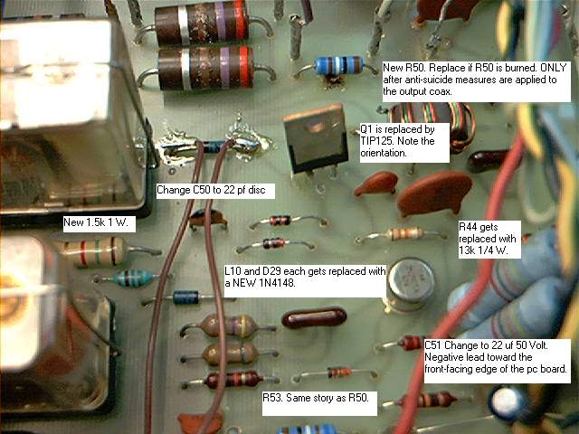
Pay no attention to the two brown wires. They feed the coil of an
auxiliary relay, used to key another unit in line.


